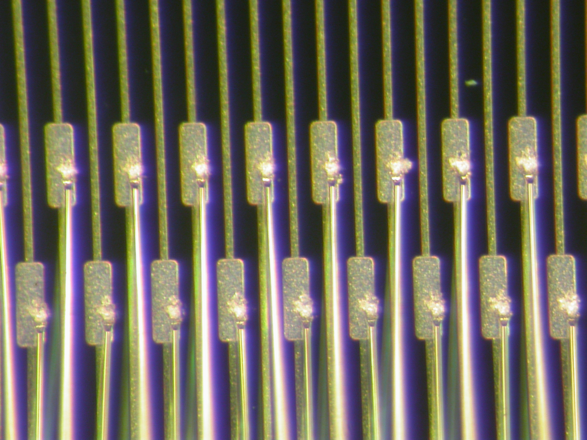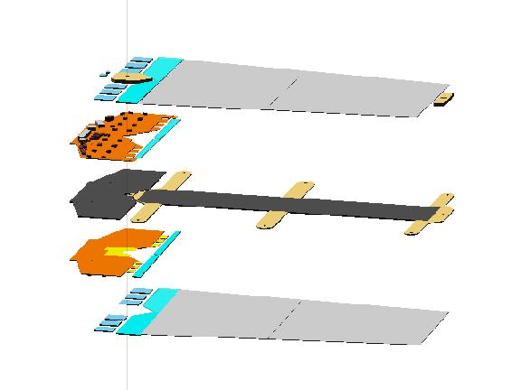
During construction four silicon strip-detectors are glued on a mechanical support frame (spine). They have to be aligned to a precision of 5 microns (perpendicular to the strips) with respect to each other. At one end the hybrid with the readout electronic is attached to the detectors. Technical drawings of the modules can be found at Liverpool.
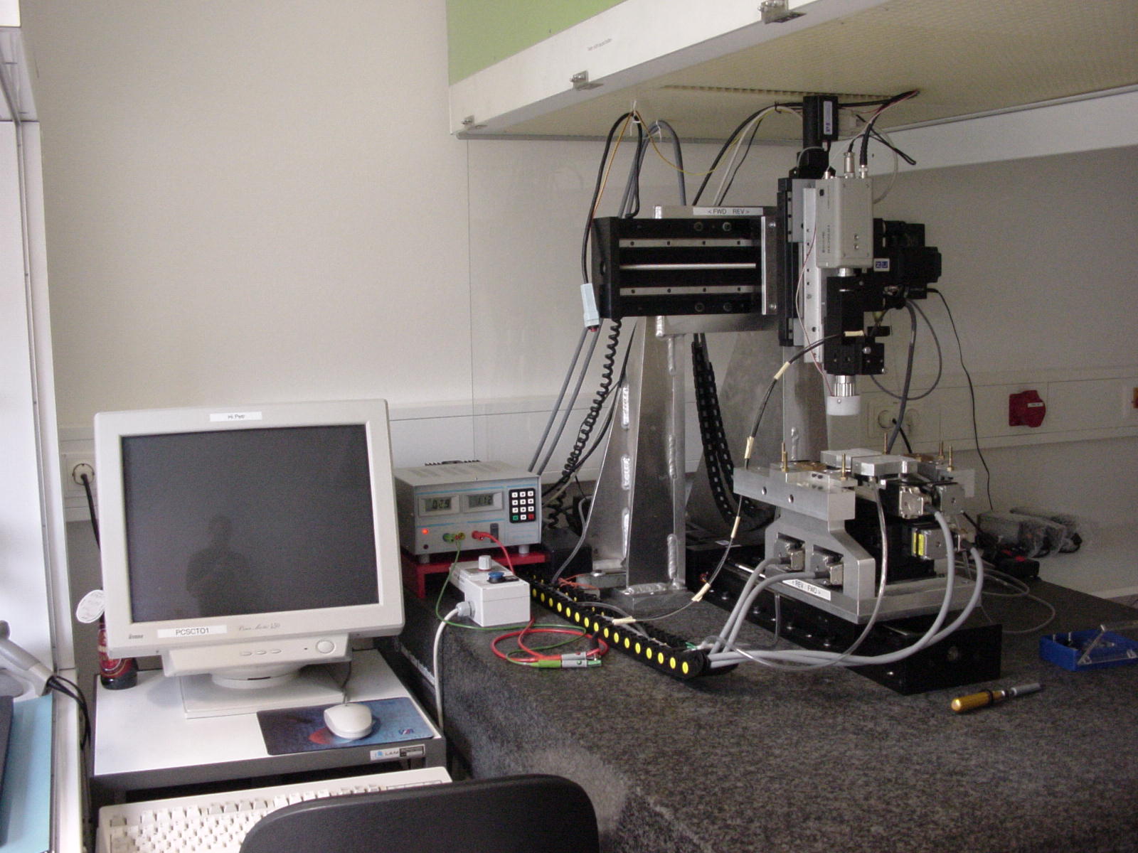
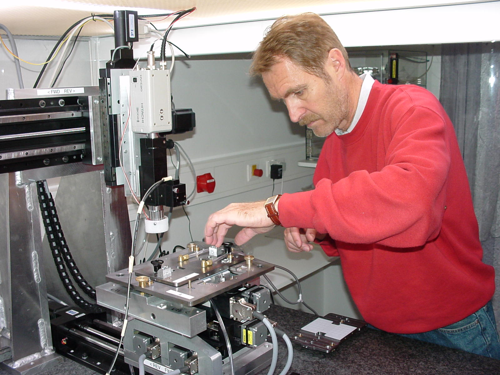
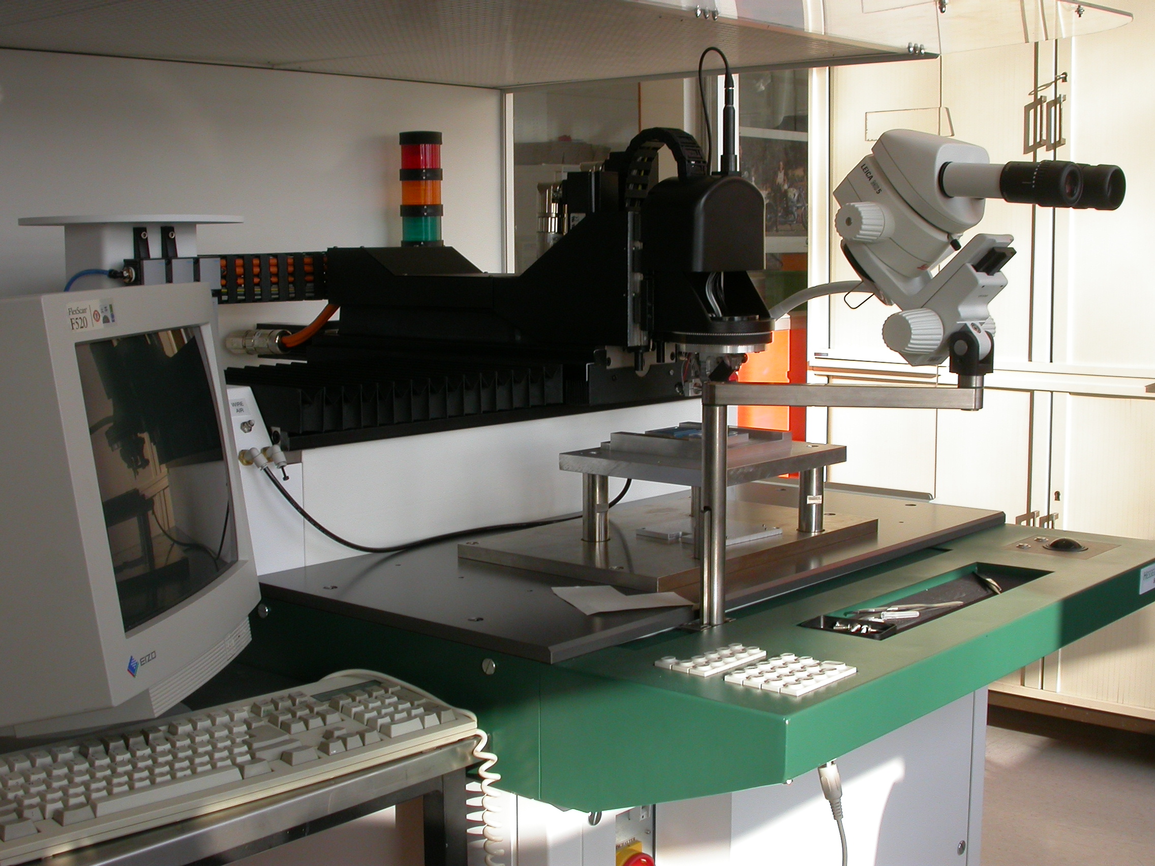
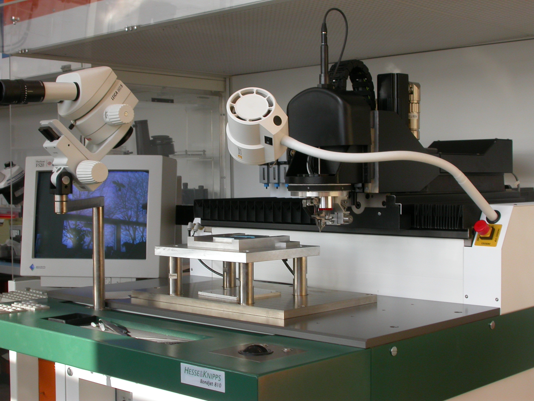
Picture of a module assemble at MPI (in the module test stand):
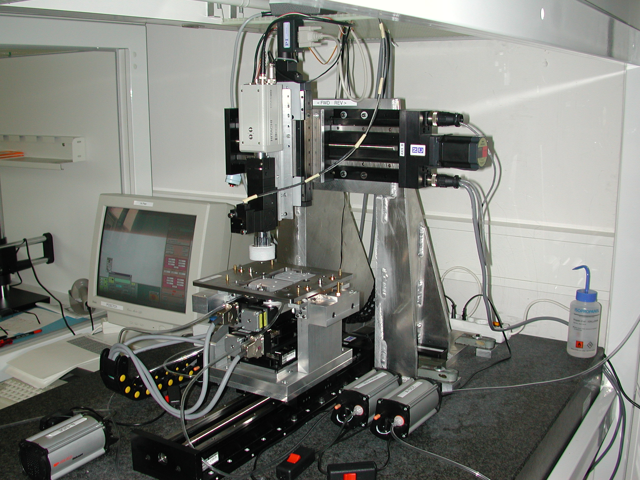
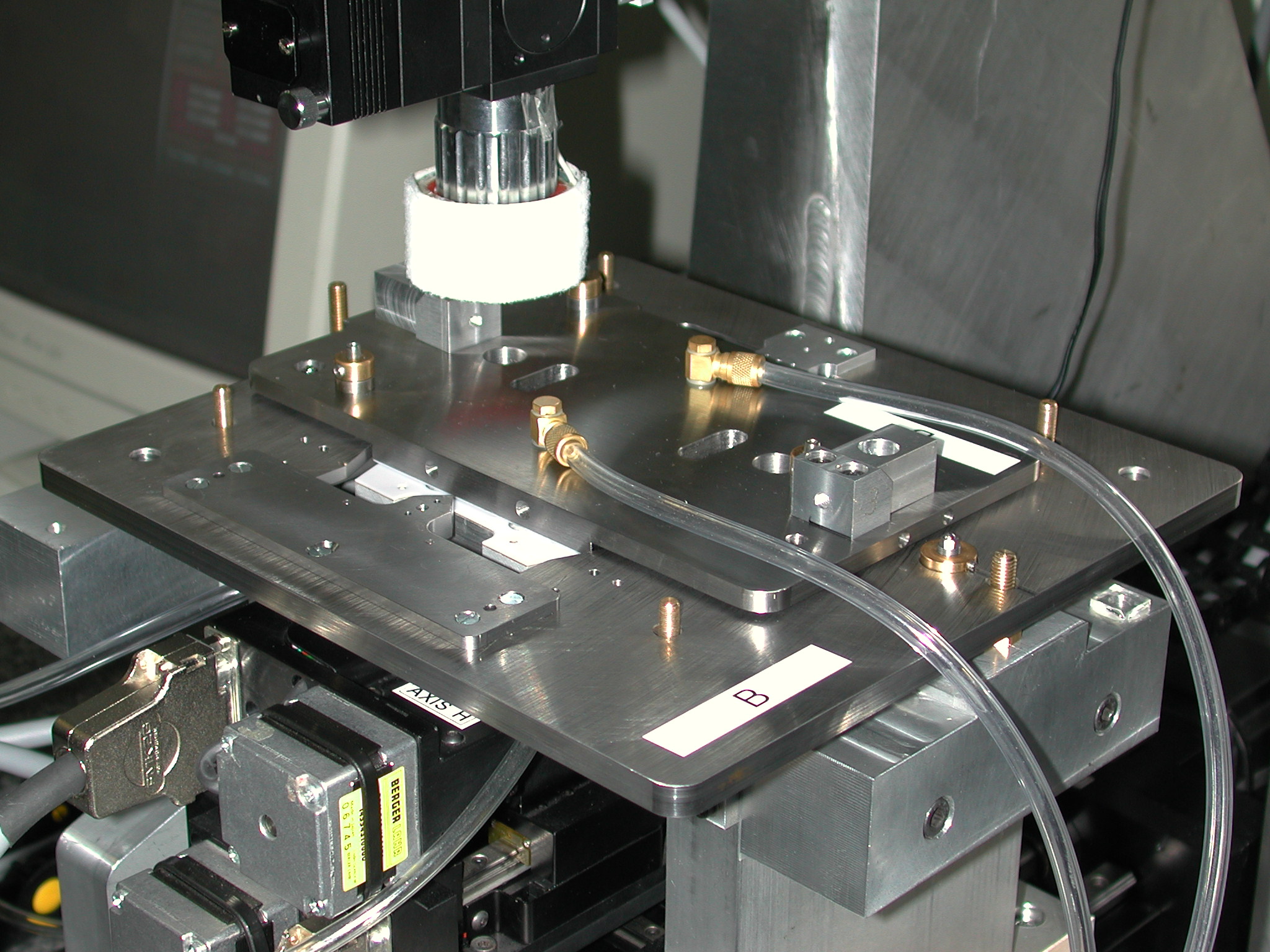
The assembly stage used is a copy of the Manchester Setup: Two detectors are placed on vacuum chucks with computer controlled x-y and rotary movements. A video camera observes the fiducial marks on the detectors and a removable reference frame which serves later as assembly jig. The detectors are then automatically aligned with respect to the reference frame.
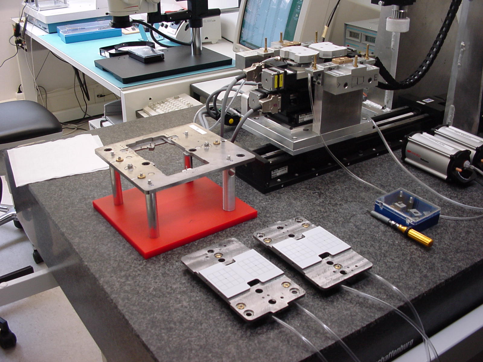
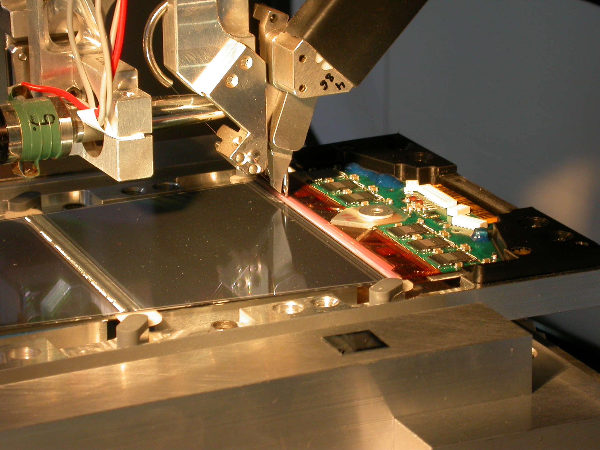
Close up of the reference frame (= turnplate) and vacuum chucks under the
video camera:
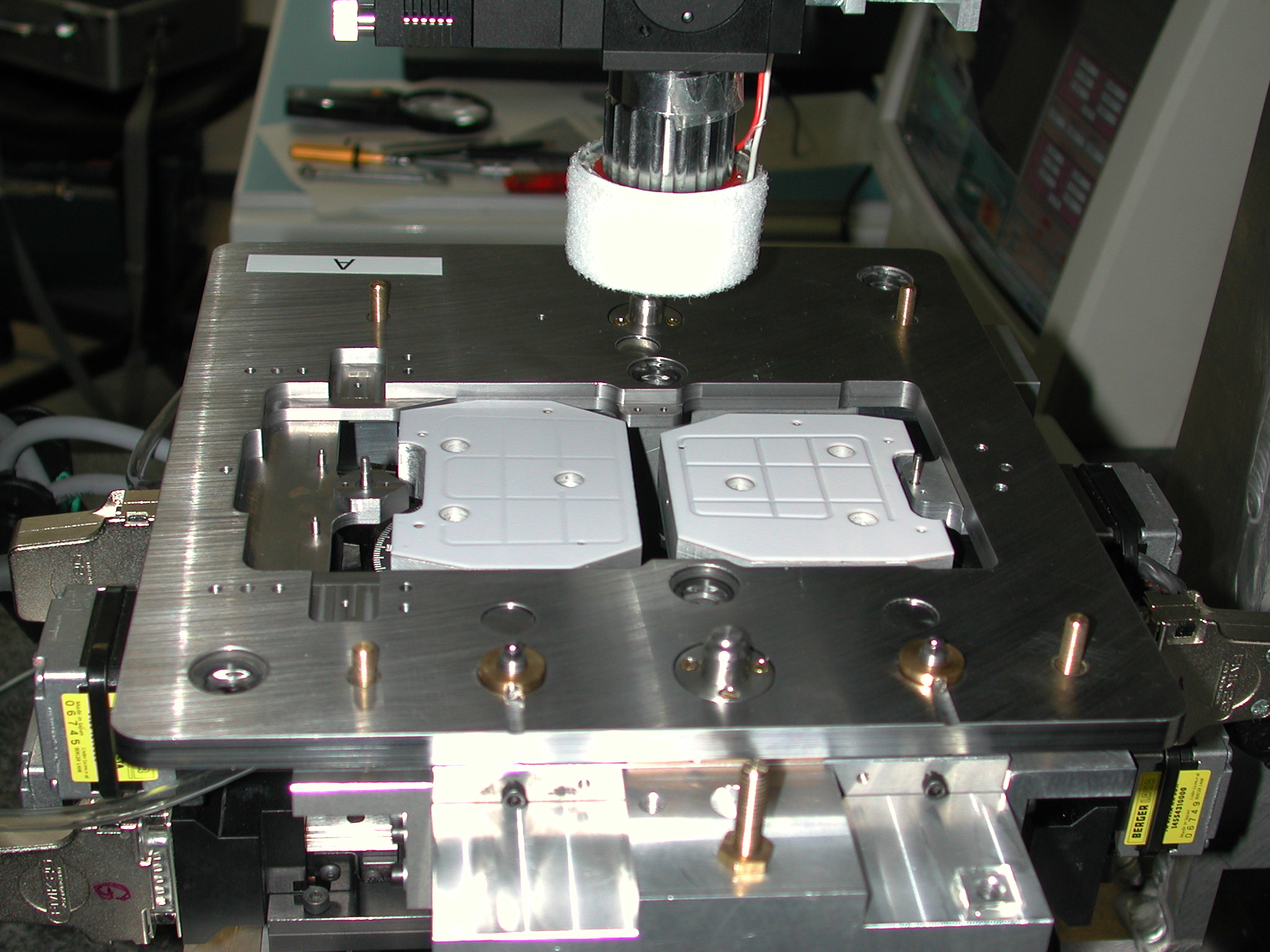
If the detectors are aligned the transfer plate is placed on top of
them. The vacuum at the detector chucks is released and the vacuum on the
transfer plate is applied. The detectors are 'transfered' onto the
transfer plate, keeping their precise alignment:
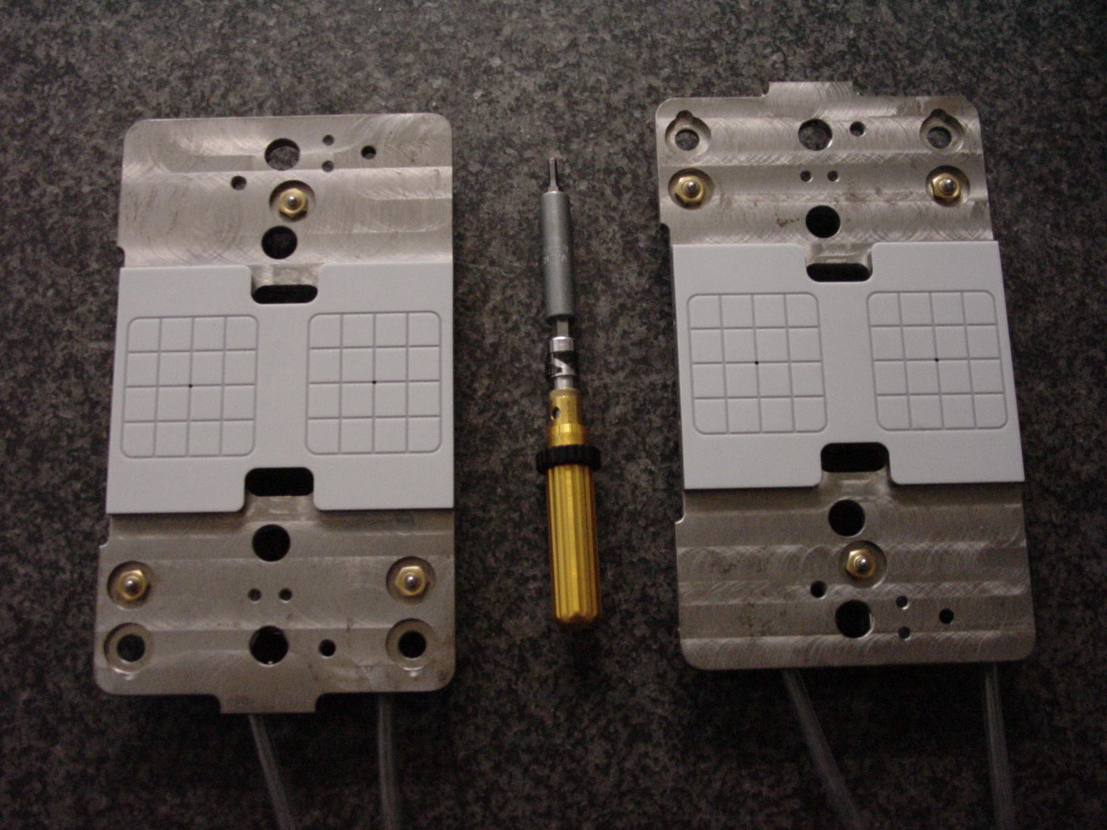
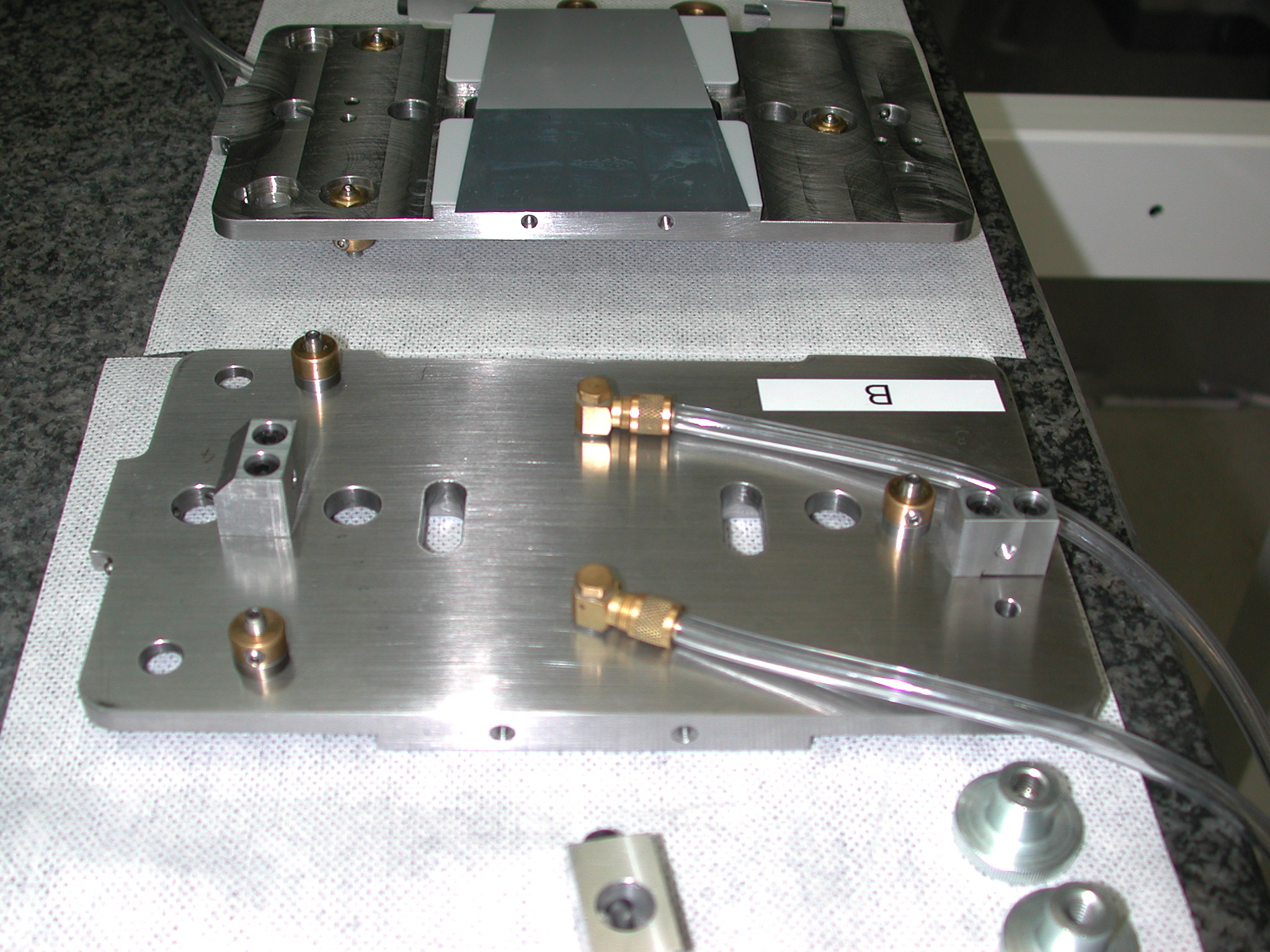
The transfer plate with the A-side detector pair is removed,
the turnplate is turned around for the B-side alignment. The B-side
detector pair is aligned and placed on its respective transfer
plate. The next picture shows the two transfer plates:
B-side(backside) and-A side (upside) with two detectors:
Finally the turnplate is removed from the assembly stations. The spine is placed into the turnplate, glue is applied and the transfer plates are placed on the A- and B-sides of the turnplate.